Thursday, November 12, 2009
new fish tank!
Pictures of the new fishtank! Apparently blogspot wants to butcher the preview images, so, just click on em to actually see them!
Wednesday, November 4, 2009
arduino/processing multichannel display and datalogging

this is VERY MUCH a work in progress! if you have any tips/clever ideas, please let me know!!!
more pics to be added shortly.
these temp sensors are usually fed with 2.5v, but they seem to work with the 3.3v as well (future plans include correcting this mismatch). I have to calibrate them and see how linear they are with the higher voltage, but for now it's working.
they've got 3 wires, red, black, and white. I've got them hooked up 3.3v->red, ground->black, and white to an analog in pin on the arduino. I think i might need some pulldown resistors on there, to clean up the output, but I haven't tried it yet.

the arduino's onboard code just reads the analog pin voltage (i t returns a value between 0 and 1024 proportional to the voltage on the pin (0-5v). It does this for 2 pins, actually, because i want to be able to scale it up to as many inputs as i need later on. then it prints a string to the serial port in the form "pin1in,pin2in,|".
i'm using Processing running on the laptop attached to the arduino via usb cable. The arduino is recognized by the computer as a serial port.
In processing, I read in the string coming from the serial port and split that string into it's component values. this happens extremely fast, and i average the values over a settable period of time. every averaging period, it writes to a graph on the screen and to a text file.
this still needs a ton of cleaning up, and there are other things I want to add, but this is the first relatively-successful iteraton, so I thought I'd post it.
arduino setup
3.3v->temp sensor->analog in

arduino code (based on Tom Igoe's examples):
void setup() {
Serial.begin(9600);
}
void loop() {
// read the analog input into a variable:
int analogValue = analogRead(0);
int analogValue1 = analogRead(1);
// print the result:
Serial.print(analogValue);
Serial.print(",");
Serial.print(analogValue1);
Serial.print(",");
Serial.println("|");
// wait 10 milliseconds for the analog-to-digital converter
// to settle after the last reading:
delay(10);
}
processing code:
import processing.serial.*;
Serial myPort;
PFont myFont;
String inString="1";
int lf = 10;
float a, millistgt, millis1, pavgs, pavgms;
float loopcount;
float bsum, dsum;
float b, d;
float lasta, lastc;
float lastb, lastd;
float keepa, keepc;
PrintWriter output;
float val, bval;
void setup() {
myFont = loadFont("Arial-Black-18.vlw");
textFont(myFont, 18);
myPort = new Serial(this, Serial.list()[1], 9600);
myPort.bufferUntil(lf);
output = createWriter("positions.txt");
///frameRate(10);
size(600, 400);
stroke(255);
background(192, 64, 0);
a=0;
// b=400;
// d=400;
line (0,0,0,400);
line (0,50,width,50);
line (0,100,width,100);
line (0,150,width,150);
line (0,200,width,200);
line (0,250,width,250);
line (0,300,width,300);
line (0,350,width,350);
keepa=0;
loopcount=0;
bsum=0;
dsum=0;
//inString="0";
}
void draw() {
pavgs=.25; //<--------------------------------avg (reporting) time in seconds pavgms=pavgs*1000;
millistgt=millis()+pavgms;
loopcount=0;
keepa++;
lasta=a;
lastb=b;
lastd=d;
a++;
bsum=0;
dsum=0;
millis1=millis();
if (millis1<3000){
delay(1500);}
do{
millis1=millis();
// val=int(inString); // Converts and prints float
// val = Integer.parseInt(inString,3);
//val=Float.parseFloat(inString);
//bval=mouseY;
b=val;
d=bval;
bsum=bsum+b;
dsum=dsum+d;
loopcount++;
}
while (millistgt>millis1);
b=bsum/loopcount;
d=dsum/loopcount;
//float lastaf=Float.parseFloat(lasta);
stroke(255);
line(lasta, lastb, a, b);
stroke(0);
line(lasta, lastd, a, d);
// fill(0);
// rect(0, 25, 300, 50);
//fill(255);
//text("val: " + val + "bval:" + bval, 10,50);
if (a > 600) {
background(192, 64, 0);
line (0,0,0,400);
line (0,50,width,50);
line (0,100,width,100);
line (0,150,width,150);
line (0,200,width,200);
line (0,250,width,250);
line (0,300,width,300);
line (0,350,width,350);
a=0;
}
}
//if millis1<
// Write the coordinate to a file with a
// "\t" (TAB character) between each entry
output.println(a + "," + keepa + "," + val + "," + bval+","+millis1);
}
void keyPressed() { // Press a key to save the data
output.flush(); // Write the remaining data
output.close(); // Finish the file
exit(); // Stop the program
}
void serialEvent(Serial p) {
String myString = p.readStringUntil(124); //the ascii value of the "|" character
if(myString != null ){
myString = trim(myString); //remove whitespace around our values
int inputs[] = int(split(myString, ","));
//now assign your values in processing
//if(inputs.length == 2){
val = inputs[0];
bval = inputs[1];
fill(0);
rect(0, 25, 300, 50);
fill(255);
text("val: " + val + "bval:" + bval, 10,50);
}
//inString = p.readString();
//val = p.read(); // read it and store it in val
}
here's what it draws to the screen:
 I still need to get it scaled correctly, and put labels on the graph axes. And pick some better colors.
here's an example of the current log file:
 it displays reading number, another reading number i was using for diagnostics, reading1, reading2, and the total elapsed time in milliseconds. I need to get the time variable worked out in a more useful way, and I think I want to include the total number of readings that went into each averaged point as well.
much thanks to the arduino and processing communities for all their help so far. Feel free to use bits of this mess.
Home made electric smoker with PID feedback temperature control
updated again 9/17/12 (at the bottom)

I know this isn't the newest idea on the block (heck, Alton Brown made one of these things), but I thought I'd post a writeup of my home-made electric smoker with PID temperature control, because it's slightly different from the standard version.
WARNINGS:
Before I get started, I'd like to offer a couple of warnings.
This project requires messing around with 115v mains current.
This project involves VERY hot items, and a definite possibility of fires, do NOT operate this thing indoors, or anywhere flammable.
I assume no responsibility whatsoever for anything you may do or that may happen as a result of your attempts to follow this build process
MATERIALS:
That's all you NEED to make this run (need is a questionable word. you can do all of this without the PID or anything like that, but that's boring) . The following items are things that I've added that make things easier to deal with.
CONSTRUCTION:
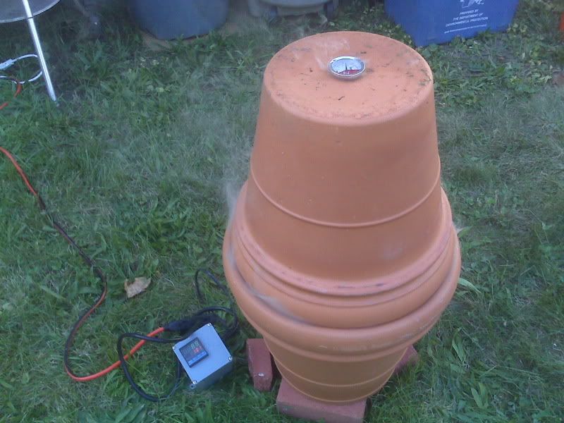
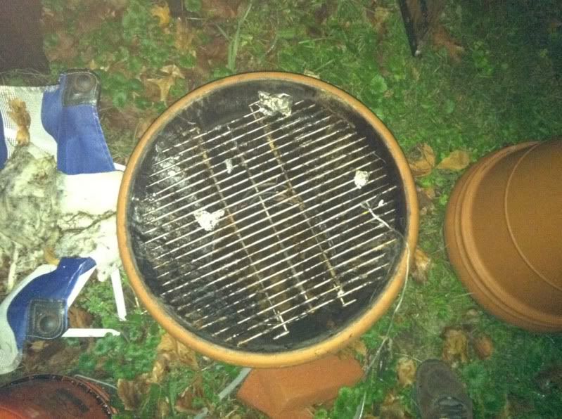
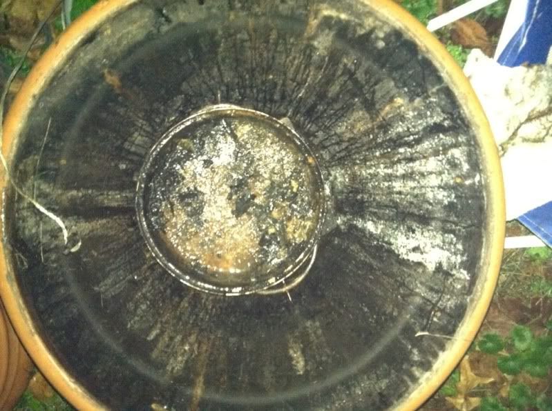
Most of this is very straightforward. Set the bottom planter on some bricks, pull the heating element out of the hot plate and put it on some brick pieces inside the bottom planter. Try to make it nice and stable. My hot plate had some temp control electronics (a simple bi-metallic strip) and a lamp attached to it. I ditched all that, but kept the fiber-coated heat resistant wiring. I ran the hi-temp wires from the hot plate element through the bottom hole, where I soldered them to some standard heavy wire to form the hot plate power cord. The chip pan goes straight on top of the hot plate element, the grate wedges in to the bottom planter, and the top planter just sits right on top.
At this point, you could just plug the hot plate in, and the whole thing would get VERY hot (350-400*F at least), and you'd probably burn out the hot plate element after a while. What you need is some sort of temperature control. The hot plate likely came with a simple bi metallic strip and knob. The problem with using these is that there's really no simple, effective way to do it. If you put the knob/strip outside the planter, it never gets hot and doesn't do anything. If you put it inside, it's impossible to adjust without largely disassembling everything and probably burning all the hair off your hand. Further, if you move the strip physically a few inches toward or away from the element, your temp control completely changes. And finally, even if you can get it all nailed down, it's still complete trial and error trying to get the temperature set to where you want it, and you've got no way to adjust for temperature creeping up or down without physically being there to fiddle with it. This is where our friend the PID temperature controller comes in.
WIRING/PID HOOKUP:
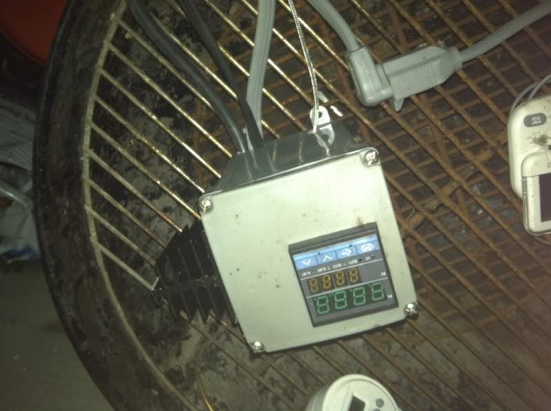
The remaining construction involves hooking up the PID.
PID Power:
The PID runs off of standard wall current, so you could have just one plug that powers both the PID and the hot plate. For various reasons, I chose to have them separate. One plug powers up the PID, and a different one feeds power through the temp controller to the hot plate. This way I can have the PID on and mess with it's settings without having mains voltage elsewhere in the box. Anyway, run power to the appropriate terminals on teh back of the PID.
Thermocouple:
After power, you need to hook up the thermocouple. My PID came with a nice K-type thermocouple with about 4 feet of braided-steel-encased wire, which is perfect for my setup, but not long enough. You need to be slightly careful about extending the wire, as variations in resistance will change the temperature reading. I just used about 6 feet of half decent speaker wire soldered to the original thermocouple wire, and it seems to be fine. Hook the + and - thermocouple wires to the terminals at the back of the PID. Pay attention to the polarity. If you have it backwards, the temperature reading will go down as temp rises, and things will go quite badly awry.
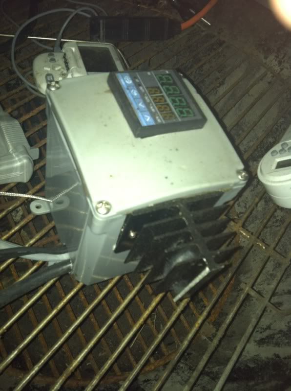
Relay and Hotplate Power:
My PID has an internal SSR output, basically it puts out 12vdc when it wants to be heating, and 0vdc when it doesn't. This is perfect, because it can serve as a trigger signal to the SSR with no modification. The Chinese instructions that came with the PID didn't make this super clear, so I wasted some time and effort hooking up a 12vdc trigger power supply that I didn't end up needing. Anyway, wire the positive and negative SSR outputs from the PID to the trigger side of the relay. Take the cord you want to use for the hot plate power supply and split one of the conductors, attaching each end to the output side of the relay. Now when the relay closes, you get mains current flowing through the hot plate. When it opens, the hot plate shuts off. Be aware that any time you have this plugged in, you WILL have live mains current in the hotplate power wire, even if the PID is not calling for heat.
FINAL ASSEMBLY:
Box all of this up inside the enclosure, hook up your high-amperage connectors to the hot plate and the relay, and you're ready to test. My PID has an auto-tune feature, but it doesn't seem to work very well for this application. Maybe it will work better for you... I have achieved pretty good control results through trial and error with P=3, I=1, and D=1. Very basic PID control theory is discussed here: wikipedia.
For best results, put the thermocouple right near the grate surface, but not touching either the grate or the meat. Plug in your thermometers and your dataloggers and have at it!
Here are a couple data plots from smokes I have done. You can see that the PID does a very good job controlling the temperature inside the smoker, even if the outdoor temperature changes significantly. The major changes in logged temp are either from me opening the smoker to poke at things, or from me changing the PID set point.
This plot was from earlier, when I hadn't got the PID values settled down quite as well:

This plot is a later smoke, with better temp control:

So far this whole setup has been very safe and reliable. As I said, Josh got zapped by the connector once. It has never caught fire on me, but it certainly could, so I never operate it within about 10 feet of the house, just to be safe.
UPDATE: I ended up putting a second burner in next to the original one, and I can hit temps near 400*F now. The only additional electronics I needed to deal with for the upgrade was to order a higher-amp rated SSR, and install a heat sink for it (I tried it once without the better relay and heat sink, and the whole thing melted down).
UPDATE2: I also ended up cutting up a weber charcoal grill grate to make it fit, which works better. The smoker I made for my dad is larger, and a regular weber grill grate fits in it perfectly without modification (I think his uses 21 or 22" planters). I also switched to the coil-style heating elements I mentioned in the build log. They do seem to both heat faster and last longer. I scavenged them from a couple of $15 hot plates I bought off of amazon.
UPDATE3: Hackaday picked this up, so I thought I'd add a few more pics. Pardon the mess, I forgot to put the tarp over the smoker, and it's been raining.

 9/17/12 update
here's a little time-lapse vid I made of me making 4 smoker brains for family members:
9/17/12 update
here's a little time-lapse vid I made of me making 4 smoker brains for family members:

I know this isn't the newest idea on the block (heck, Alton Brown made one of these things), but I thought I'd post a writeup of my home-made electric smoker with PID temperature control, because it's slightly different from the standard version.
WARNINGS:
Before I get started, I'd like to offer a couple of warnings.
This project requires messing around with 115v mains current.
This project involves VERY hot items, and a definite possibility of fires, do NOT operate this thing indoors, or anywhere flammable.
I assume no responsibility whatsoever for anything you may do or that may happen as a result of your attempts to follow this build process
MATERIALS:
- 2 large ceramic planters
- hot plate
- bricks
- grate
- chip pan
- water dish
- PID temperature controller and thermocouple
- Solid state relay
- enclosure
- high amperage quick connector
That's all you NEED to make this run (need is a questionable word. you can do all of this without the PID or anything like that, but that's boring) . The following items are things that I've added that make things easier to deal with.
- remote meat thermometer
- datalogging
CONSTRUCTION:
Most of this is very straightforward. Set the bottom planter on some bricks, pull the heating element out of the hot plate and put it on some brick pieces inside the bottom planter. Try to make it nice and stable. My hot plate had some temp control electronics (a simple bi-metallic strip) and a lamp attached to it. I ditched all that, but kept the fiber-coated heat resistant wiring. I ran the hi-temp wires from the hot plate element through the bottom hole, where I soldered them to some standard heavy wire to form the hot plate power cord. The chip pan goes straight on top of the hot plate element, the grate wedges in to the bottom planter, and the top planter just sits right on top.
At this point, you could just plug the hot plate in, and the whole thing would get VERY hot (350-400*F at least), and you'd probably burn out the hot plate element after a while. What you need is some sort of temperature control. The hot plate likely came with a simple bi metallic strip and knob. The problem with using these is that there's really no simple, effective way to do it. If you put the knob/strip outside the planter, it never gets hot and doesn't do anything. If you put it inside, it's impossible to adjust without largely disassembling everything and probably burning all the hair off your hand. Further, if you move the strip physically a few inches toward or away from the element, your temp control completely changes. And finally, even if you can get it all nailed down, it's still complete trial and error trying to get the temperature set to where you want it, and you've got no way to adjust for temperature creeping up or down without physically being there to fiddle with it. This is where our friend the PID temperature controller comes in.
WIRING/PID HOOKUP:
The remaining construction involves hooking up the PID.
PID Power:
The PID runs off of standard wall current, so you could have just one plug that powers both the PID and the hot plate. For various reasons, I chose to have them separate. One plug powers up the PID, and a different one feeds power through the temp controller to the hot plate. This way I can have the PID on and mess with it's settings without having mains voltage elsewhere in the box. Anyway, run power to the appropriate terminals on teh back of the PID.
Thermocouple:
After power, you need to hook up the thermocouple. My PID came with a nice K-type thermocouple with about 4 feet of braided-steel-encased wire, which is perfect for my setup, but not long enough. You need to be slightly careful about extending the wire, as variations in resistance will change the temperature reading. I just used about 6 feet of half decent speaker wire soldered to the original thermocouple wire, and it seems to be fine. Hook the + and - thermocouple wires to the terminals at the back of the PID. Pay attention to the polarity. If you have it backwards, the temperature reading will go down as temp rises, and things will go quite badly awry.
Relay and Hotplate Power:
My PID has an internal SSR output, basically it puts out 12vdc when it wants to be heating, and 0vdc when it doesn't. This is perfect, because it can serve as a trigger signal to the SSR with no modification. The Chinese instructions that came with the PID didn't make this super clear, so I wasted some time and effort hooking up a 12vdc trigger power supply that I didn't end up needing. Anyway, wire the positive and negative SSR outputs from the PID to the trigger side of the relay. Take the cord you want to use for the hot plate power supply and split one of the conductors, attaching each end to the output side of the relay. Now when the relay closes, you get mains current flowing through the hot plate. When it opens, the hot plate shuts off. Be aware that any time you have this plugged in, you WILL have live mains current in the hotplate power wire, even if the PID is not calling for heat.
FINAL ASSEMBLY:
Box all of this up inside the enclosure, hook up your high-amperage connectors to the hot plate and the relay, and you're ready to test. My PID has an auto-tune feature, but it doesn't seem to work very well for this application. Maybe it will work better for you... I have achieved pretty good control results through trial and error with P=3, I=1, and D=1. Very basic PID control theory is discussed here: wikipedia.
For best results, put the thermocouple right near the grate surface, but not touching either the grate or the meat. Plug in your thermometers and your dataloggers and have at it!
Here are a couple data plots from smokes I have done. You can see that the PID does a very good job controlling the temperature inside the smoker, even if the outdoor temperature changes significantly. The major changes in logged temp are either from me opening the smoker to poke at things, or from me changing the PID set point.
This plot was from earlier, when I hadn't got the PID values settled down quite as well:

This plot is a later smoke, with better temp control:

So far this whole setup has been very safe and reliable. As I said, Josh got zapped by the connector once. It has never caught fire on me, but it certainly could, so I never operate it within about 10 feet of the house, just to be safe.
UPDATE: I ended up putting a second burner in next to the original one, and I can hit temps near 400*F now. The only additional electronics I needed to deal with for the upgrade was to order a higher-amp rated SSR, and install a heat sink for it (I tried it once without the better relay and heat sink, and the whole thing melted down).
UPDATE2: I also ended up cutting up a weber charcoal grill grate to make it fit, which works better. The smoker I made for my dad is larger, and a regular weber grill grate fits in it perfectly without modification (I think his uses 21 or 22" planters). I also switched to the coil-style heating elements I mentioned in the build log. They do seem to both heat faster and last longer. I scavenged them from a couple of $15 hot plates I bought off of amazon.
UPDATE3: Hackaday picked this up, so I thought I'd add a few more pics. Pardon the mess, I forgot to put the tarp over the smoker, and it's been raining.
 9/17/12 update
here's a little time-lapse vid I made of me making 4 smoker brains for family members:
9/17/12 update
here's a little time-lapse vid I made of me making 4 smoker brains for family members:
Fish tanks!
Well, I figured I should post at least some sort of a baseline for how the tanks are looking at the moment. Pardon the cellphone pics, I'll get some better ones soon.
Josh's "old" reef tank (39 gal):
 Looking pretty decent. Needs a bit of a cleaning, and we think the bulb in the light is going, because some of the hard corals that need more intense light aren't doing so well at the moment.
The new upstairs reef tank (50 gal cube):

 As you can see, it's cycling. A bunch of snails and hermit crabs, and one or 2 soft corals just for the hell of it. Hopefully in the next few weeks we can clean it up and start moving over more stuff from the old tank. Currently we are debating whether or not the bulb (ushio 14k) is too yellow.
And finally the freshwater tank downstairs:
 I'm having a hard time keeping fish alive in it, but otherwise it's looking nice. Shrimp and plants are doing great... I'm going to add a FEW tall stemmed plants, at least in the left corner, possibly in both corners, and maybe a bit of scrubby ground cover eventually. Other than that, I just need to figure out why it seems to kill fish so effectively.

Subscribe to:
Posts (Atom)